Jeep Garage  - Jeep Forum banner

A hardware, plug & play, solution to Fog Lights + High Beams for the WL

2 reading
5.5K views 20 replies 3 participants last post by  f1anatic  
#1 · (Edited)
I am on a crusade to make my fog lights great again. In my WK2, I could just re-configure the BCM with AlfaOBD. I tried (one of the first brave soul to do it on this board - my exploits are documented on the forum here and over at 4xe) with my WL, and I had some modules refuse to proxy align. By some inspirational-magical-divine-grace I was able to restore the settings and dashboard lights fixed themselves.

2022(23-spec) WL 4XE Trailhawk. With most of the options for that year.

As you know, when you turn on the high beams (automatic), the fog lights drop out. On the WK2, I modified a flag in AlfaOBD. On the WL, it will have to be done with a hardware. I want to thank @AmauryJVL for inspiration: https://www.jeepgarage.org/threads/roof-mounted-led-bar-install.252838/ but I will be doing it differently. I did search and I came up mostly empty - people are trying to tap the interior fuses for cameras, radar, radio.

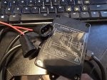
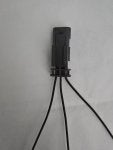
Automatic Transfer Switch DC 5V-60V (ATS) - one each per fog light.
Amazon.com: Automatic Transfer Switch DC 5V-60V ATS Automatic Transfer Switch, ATS Auto Transfer Switchs<10ms for refrigerators, Emergency Lights, etc(bicut DC). : Patio, Lawn & Garden

Image


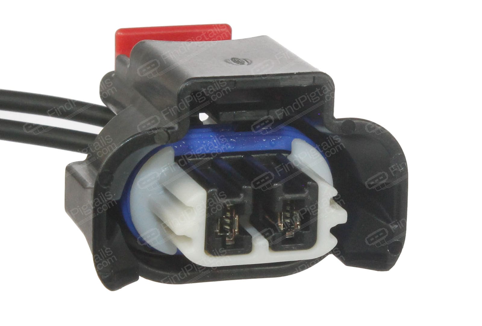
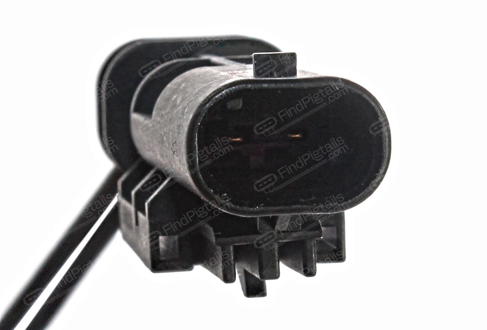
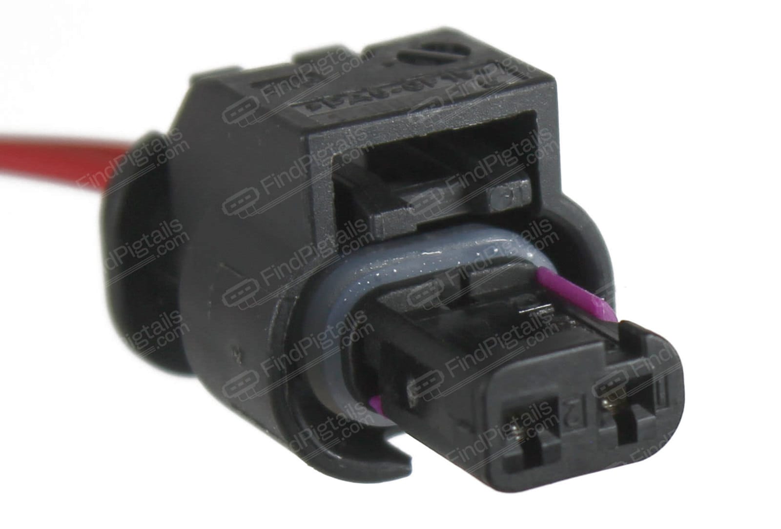
Proper wiring (say 16 AWG). Proper factory connections. I will get the proper factory connectors so everything is plug-n-play.
  • Frequently Used Power - the original factory harness for fog lights
  • Stand-by Power - auxiliary power from a tapped fuse.
These fog lights are drawing 1-3 Amps (at most) - just by reference to the headlights which are protected by a 20 Amp.

WHICH FUSE(s) TO TAP ? Obviously it needs to be a switched power.

I could keep it simple - the headlight fuses. There's a 10 Amp Left and a 10 Amp Right. I could do front grille shutters. Afterall I would like my engine cooled (open grille shutters) at all times. But I would prefer either something even less consequential than grille shutters - preferably for something that I know I do not have on my vehicle. For instance my BSM Valves and another BSM spot are actually empty.

COMMUNITY QUESTION # 1 - Which fuse have you taped before for such projects ?
COMMUNITY QUESTION # 2 - Which blank spots are actually powered ?

References:
2023 Grand Cherokee Fuse Box diagram and explanations 2023 Jeep Grand Cherokee fuse box diagram - StartMyCar
The attachment is my actual fuse box in the "anatomically correct" positioning for easy identification. To the left of the fuse box (as photographed) is the windshield, to the right, the front of the car. The 5 large metal bus connectors point towards the engine block.
 

Attachments

#2 ·
As an update, I removed the F54 Microfuse Headlamp LT to see what happened. Both the headlamp and the fog light are protected by the same 20 Amp fuse. The left side of the car was dark. You'd think it would be simple to tap the same fuse. I will have to double check, but it appears to be powered when the car is off. Especially since one can turn on the headlamps - but not the fog lights - with the car engine and aux power off by rotating the dial. One fear is that tapping the same headlamp fuse for backup power would create a loop of continuously running fog lights - switching between main and aux power.

It appears that all other blank spots, including for equipment that I do not have, are not powered.
 
#4 ·
The connector above is plugged into the fog lights on my 2023 Grand Cherokee 4XE.
This is what the fog light looks like. It appears to be an H11. But I tried an H11 kit from my 2014 Grand Cherokee and it doesn't fit. The pins (blades) are closer together by 2 mm or so. The male connector also looks like a ATX connector.

So what is the base of the fog lights and what is the male connector ? Thank you.

Image
 
#6 · (Edited)
What matching connector do I plug this shit in ? What kind of female connector do I need?

FOG LIGHT CONNECTOR type J55C2.
This is the "male" connector that is installed on the OEM / factory harness. Confirmed by my own photos and online connector vendor.

FOG LIGHT CONNECTOR type F23C2
This is the "female" connector that is on the back of the OEM / factory fog lights manufactured by Myotek. Confirmed by my own photos and online connector vendor.

to be verified -
SIDE MARKER CONNECTOR is type L64A2

Jeep Fog Lights are made by MYOTEK Myotek Products – Myotek

Jeep Fog Lights appear to pull 9 Watts at 5 VDC based on the markings.
What I measured is different.

With the engine on (hood open), Low Beams on, Fog Lights on - the Voltage to the Fog Lights is 13.8 V or thereabouts. When the High Beams are on, Fog Lights turn off and the Voltage drops to a constant 8.4 V or so.

Image
 
#7 · (Edited)
After checking again this week with Alfa OBD and TAZER for any updates, and be told to remain patient, I am not going to wait for aftermarket support for BCM mods. I was, as documented elsewhere on this forum, the ID-10-T who tried to get it done, about a year today, with a forum colleague and kind soul. We used a suite of software, 2 appropriate OBD-2 Bluetooth modules, AlfaOBD, AutoAuth, we got past the SGW, we modified the flag for fog lights, but it failed on Proxy Alignment. Earlier this week, the Alfa OBD guru (Alexey) confirmed that the issue of Proxy Alignment is still there:

Hello,
Basically it is possible to unlock the SGW with a second device connected in parallel with AlfaOBD/OBDLink MX+ and make changes to the body computer configuration. Although, the proxy alignment is failing on the ABS, most probably because the ABS requires FD-CAN communication only. I have no solution at the moment, working on it…
Regards,

Alexey Chernikov
AlfaOBD
This will be an expensive alternative due to the ridiculous connector prices, but I am freakin' doing it. 60% cheaper than the Mopar Micropod.

Automatic Transfer Switch DC 5V-60V (ATS) - one each per fog light
Image


FOG LIGHT CONNECTOR type F23C2 to be connected to ATS SWITCH Frequently Used Power - DC INPUT 1
This is the "female" connector that is on the back of the OEM / factory fog lights manufactured by Myotek. Confirmed by my own photos and online connector vendor.

FOG LIGHT CONNECTOR type J55C2 to be connected to ATS SWITCH DC OUTPUT Load
This is the "male" connector that is installed on the OEM / factory harness. Confirmed by my own photos and online connector vendor.

Next Steps:
1) Verify connector type and 12V on the side marker rail. Who needs side markers anyways?
2) Apparently, the findpigtails vendor cannot find me the mating connector, on the back of the side marker. The good news is that they are rather inexpensive if I have to modify 2 of them and make my own connectors. But I'd rather pay and be done.
3 A ) If Steps 1 and 2 fail, I shall find a switched power fuse under the hood, and use a fuse tap and whatever connector I want for the Stand-by Power DC INPUT 2.
3 B) If Steps 1 and 2 fail, I shall find another commercially available connector pair for something that is accessible and on switched power under the hood. I would then use that for the Stand-by Power DC INPUT 2. Something like...the Windshield Washer Fluid pump.

If anyone in the community has any ideas where I can find these freakin' connectors cheaper than $85 a piece, this would be the time to come forward. Thank you.

SIDE MARKER CONNECTOR is type L64A2

I love the energy on this board though, and the overwhelming flow of ideas for switched power under the hood and connector types.
Apparently I am the only person who wants to mod the fog lights.
 
#8 · (Edited)
Sit Rep:

  • Side Marker Lights are powered by a 12 V infrastructure (13.x V whatever I measured).
  • Side Marker Lights when disconnected, will throw a warning (Service Left Front Light) on the dashboard. But I had it disconnected so...whatever.
  • Side Marker wires are thinner (eyeballed to maybe 18 gauge) than the Fog Light wires (eyeballed to maybe 16 gauge) though I do not expect an issue. Based on the length - under 1 foot - from where it branches off from a larger multi wire conduit, Amp Capacity appears to be safely 2 - 5 Amps based on SOURCE 1 and SOURCE 2 and SOURCE 3 and SOURCE 4. If you look above, it seems these Fog Lights are rated 9 Watt max. Last I checked, Power = Current x Voltage so back calculating based on 12 V and 9 Watts (as shown on the back of the fog light), comes out to 0.75 Amps. I think it should be OK at less than half the most restrictive published value for allowed Amperage.
  • Another contender, the horns (of which there are two, one on each side) dropped out. They got power only when pressed - which makes sense - but I don't pretend to understand PowerNet architecture either.
  • There's a lot of other wires for like the front radar and parking sensors and stuff but I am not willing to touch those.
  • I would like to avoid using an Add-a-Fuse as much as possible, despite the added costs.

Image
Image
Image
Image
 
#9 · (Edited)
More connectors coming in Friday. Theoretically I will know over the week-end if this works or not.

These repurposed connectors pictured next to the Automatic Transfer Switch actually just have a lot of dielectric grease on them - nothing that a ear-cleaning cotton swab cannot fix. As it turns out, I tried with a different set of connectors of similar shape/layout from the H11 fog lights of my WK2 but those pins/blades are spaced out 2 or so millimeters more. These ones (pictured) might just do the trick - and are from LED lights I tried out a decade ago. OPT 7 FluxBeam that had an entire spaghetti bowl of wires, capacitors and what not to make it work (internet photo attached). They were bright...but burnt out quickly and they were noisy and had a fan at the back that rusted out and locked up.

Image
 

Attachments

#12 ·
I thought I will be testing things out over the week-end but seems like there in Apple Picking with the kids in the forecast for Saturday. afternoon.

Connection wise - everything I need for one side of the car - is here. Might need some PET cable sleeving and I haven't decided if I solder or use crimp connectors but ... that's first world problems. We will see if it works. But in theory...

Image


Image
 
#13 ·
Can one be successful and fail at the same time ?

THE FAILURE
Somehow I thought these people with PIGTAILS.COM sent me the correct female connector (recipient - what's on the back of the connector). Or somehow I thought I could make it work. Nah. Yes, it was a 3 wire but I thought the configuration inside was such that I could offset the male connector on the vehicle harness and connect. Negative. Good thing I only bought one.

So this is NOT the correct connector and NOT the correct part. I will circle back to this aspect once I contact the seller.
 

Attachments

#14 · (Edited)
THE SUCCESS

As I was unable to provide STAND-BY POWER from the SIDE MARKER, I had to improvise. I tried some 12V batteries from kid ride-on toys and those had no charge. I sourced out a 12 Volt 1 Amp power source (110/110 VAC in and 12 VDC out) as a surrogate for my STAND-BY POWER from the SIDE MARKER. As such, once I connected it, the fog light lit up and would stay lit when the car was turned off. It would NOT be the case when the STAND-BY POWER is connected to the SIDE MARKER, because that's on a switched power input, just like the FREQUENTLY USED POWER. It also seems to validate that our Fog Lights are low wattage (left side, no visible difference in light output between primary and stand-by power sources) - which is good since the wires to the LED side markers are somewhat thinner.

My concept of a plan works very well. I will sort out the connector aspect and I will duplicate the parts and finalize it. Still 1-2 weeks away from a final bi-lateral installation but testing phase is done. I suppose one can tell when the electricity switches sources, based on the blinking of the fog light but I can live with that. Some day when the WL aftermarket support catches up and I can enable this via AlfaOBD, I may repurpose them, along with other connectors, for additional driving lights, or maybe they will have duties relate do solar panels and portable fridges. Who knows, one mission at a time.

As soon as I finalize the install, I will write a single, cohesive, post with the complete parts list and where people can buy them, in case anyone else is interested.
 

Attachments

#16 ·
So the connector saga. In summary, the vendor admitted a fulfillment error on their end, and are sending me the correct connector over night at no cost. I did not ask for such expedited delivery. As for the $85 dollar wrong connector ?


Image


I am sure she meant wattage not power. So if my mental calculations are correct, if they included a 10$ (or cheaper) pre-paid shipping label, with the correct connector, and request that I send it back using the pre-paid label... they would be losing money. Which means these flaming connectors are R I D I CU L O U S L Y marked up. That $85 dollar connector is probably 0.85 cents to manufacture, so maybe the Chinese make $10-15 per item sold and the reseller makes $60-65 per item sold and tariffs and taxes and freight is the rest. Not a bad deal. I should definitely consider this as a side gig. Not to mention there's like 2-3 vendors on all the IntgerWebzzz that had these connectors. I come in $20 cheaper and corner the market.

I may bitch about their prices but the experience with the vendor, its customer support, including the time to respond to questions and doing the research for me about which connectors mate with which, has been very positive.
 
#17 ·
Ever watch Shark Tank? It's interesting when they reveal their landed costs - so much less expensive than one would think. That said, companies have to pay employees, advertising, electric, website costs, etc, etc beyond the cost of the item. They aren't charities and are in place to make money. It gets eaten up quickly. Just how it works.
 
#20 · (Edited)
I was defeated, outsmarted by the Jeep. But I wasn't giving up. Frank Sinatra did it his way. Elton John was still standing. Gloria Gaynor survived. You get the drift.

f1anatic was not giving up. After several other permutations, including adding an additional "hot" from the battery and using the return through the connector (because somehow the basement ceiling fan was wired like that in my house) and it worked, all of which failed, I decided that I was going to provide Stand-By Power to the ATS directly from the battery. But wouldn't that really just keep the fog light on all the time ? Sure. Unless I could control the circuit using another circuit.

There was one piece missing. This:

Image


CONTROL SIGNAL INPUT - the low amperage Side Marker LED.
DC IN (INPUT) - the battery / fuse box bus under the hood
LOAD (OUTPUT) - connected to STAND-BY POWER of the ATS (Automatic Transfer Switch) shown above.

Image


When my lights are off (daylight, manual control etc.) the FREQUENTLY USED POWER route via the ATS has no current running, as is the STAND BY POWER which is interrupted by the CONTROL SIGNAL INPUT from the SOLID STATE RELAY. When the SOLID STATE RELAY receives "electrons" via the Side Marker Harness (because it is dark outside or manual control), it allows current to travel via the STAND BY POWER route, and the ATS decides which is used when.
 
#21 ·
I will be buying parts to duplicate on the other side of the car. In theory, I can make do with just additional connectors only, and use this setup with different wiring. However, I really enjoy having a set of spare parts with me, in case one ever gives up. I will build my own harness using Home Depot's finest wires, unless I can repurpose the HID kit that I had on my Subaru Legacy GT. The spirit of which already lives in this 4xe Jeep, though he harness seems a bit short. The connectors will be reused from the Subaru, that's for sure. No factory Jeep parts were hurt in the filming and experimenting with the fog lights.