More details on troubleshooting the p0101 from the alldatadiy subscription
Diagnostic Test*
Section 1. DTC IS ACTIVE*
Ignition on, engine not running.
With the scan tool, clear DTCs in the Engine Control Module (ECM).
Start the engine and allow it to reach normal operating temperature.
With the scan tool, select View DTCs.
Is the status Active for this DTC?*
Yes*
Go To Section 2
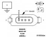
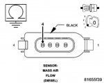
Section 2. (K157) MASS AIR FLOW SENSOR SIGNAL CIRCUIT SHORTED TO VOLTAGE
(refer to Section 2 picture)
Turn the ignition off.
Disconnect the Mass Air Flow Sensor harness connector.
Turn the ignition on.
Measure the voltage of the (K157) Mass Air Flow Sensor Signal circuit in the Mass Air Flow Sensor harness connector.
Is there any voltage present?
Yes
Repair the (K157) Mass Air Flow Sensor Signal circuit for a short to voltage.
Perform the ECM Verification Test Ver. 1. See: Verification Tests\Powertrain Verification Test
No
Go to Section 3
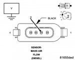
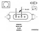
Section 3. (K957) MASS AIR FLOW SENSOR GROUND CIRCUIT SHORTED TO VOLTAGE
(refer to Section 3 picture)
Measure the voltage of the (K957) Mass Air Flow Sensor Ground circuit in the Mass Air Flow Sensor harness connector.
Is there any voltage present?
Yes
Repair the (K957) Mass Air Flow Sensor Ground circuit for a short to voltage.
Perform the ECM Verification Test Ver. 1. See: Verification Tests\Powertrain Verification Test
No
Go to Section 4
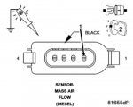
Section 4. (F944) IGNITION SWITCH OUTPUT (RUN-START) CIRCUIT OPEN OR HIGH RESISTANCE
(refer to Section 4 picture)
Using a 12 volt test light connected to ground, check the (F944) Ignition Switch Output (Run-Start) circuit in the Mass Air Flow Sensor harness connector.
NOTE: The test light should be illuminated and bright. Compare the brightness to that of a direct connection to the battery.
Is the test light illuminated and bright?
Yes
Go to Section 5
No
Repair the (F944) Ignition Switch Output (Run-Start) circuit for an open circuit or high resistance.
Perform the ECM Verification Test Ver. 1. See: Verification Tests\Powertrain Verification Test
Section 5. (K157) MASS AIR FLOW SENSOR SIGNAL CIRCUIT OPEN OR HIGH RESISTANCE
(refer to Section 5 picture)
Measure the resistance of the (K157) Mass Air Flow Sensor Signal circuit between the Mass Air Flow Sensor harness connector and the Engine Control Module (ECM) harness connector.
Is the resistance below 10.0 ohms?
Yes
Go to Section 6
No
Repair the (K157) Mass Air Flow Sensor Signal circuit for an open circuit or high resistance.
Perform the ECM Verification Test Ver. 1. See: Verification Tests\Powertrain Verification Test
Section 6. (K957) MASS AIR FLOW SENSOR GROUND CIRCUIT OPEN OR HIGH RESISTANCE
(refer to Section 6 picture)
Measure the resistance of the (K957) Mass Air Flow Sensor Ground circuit between the Mass Air Flow Sensor harness connector and the Engine Control Module (ECM) harness connector.
Is the resistance below 10.0 ohms?
Yes
Go to Section 7
No
Repair the (K957) Mass Air Flow Sensor Ground circuit for an open circuit or high resistance.
Perform the ECM Verification Test Ver. 1. See: Verification Tests\Powertrain Verification Test
Section 7. (K157) MASS AIR FLOW SENSOR SIGNAL CIRCUIT SHORTED TO GROUND
(refer to Section 7 picture)
Measure the resistance between ground and the (K157) Mass Air Flow Sensor Signal circuit in the Mass Air Flow Sensor harness connector.
Is the resistance above 10.0 ohms?
Yes
Go to Section 8
No
Repair the (K157) Mass Air Flow Sensor Signal circuit for a short to ground.
Perform the ECM Verification Test Ver. 1. See: Verification Tests\Powertrain Verification Test
Section 8. (K157) MASS AIR FLOW SENSOR SIGNAL CIRCUIT SHORTED TO THE (K957) MASS AIR FLOW SENSOR GROUND CIRCUIT
(refer to Section 8 picture)
Measure the resistance between the (K157) Mass Air Flow Sensor Signal circuit and the (K957) Mass Air Flow Sensor Ground circuit in the Mass Air Flow Sensor harness connector.
Is the resistance above 10.0 ohms?
Yes
Go to Section 9
No
Repair the (K157) Mass Air Flow Sensor Signal circuit for a short to the (K957) Mass Air Flow Sensor Ground circuit.
Perform the ECM Verification Test Ver. 1. See: Verification Tests\Powertrain Verification Test
Section 9. MASS AIR FLOW SENSOR
Turn the ignition off.
Connect the Engine Control Module (ECM) connector.
Replace the Mass Air Flow Sensor.
Turn the ignition on.
With the scan tool, Clear DTCs.
Start the engine and allow it to reach normal operating temperature.
With the scan tool, select View DTCs.
Is the status Active for this DTC?
Yes
Go to Section 10
No
Test Complete.
Perform the ECM Verification Test Ver. 1. See: Verification Tests\Powertrain Verification Test
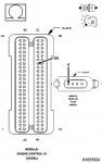
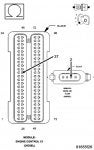
Section 10. ENGINE CONTROL MODULE (ECM)
Using the wiring diagram/schematic as a guide, inspect the wiring and connectors between the Mass Air Flow Sensor and the Engine Control Module (ECM).
Look for any chafed, pierced, pinched, or partially broken wires.
Look for broken, bent, pushed out or corroded terminals.
Monitor the scan tool data relative to this circuit and wiggle test the wiring and connectors.
Look for the data to change or for the DTC to reset during the wiggle test.
Search for any Technical Service Bulletins that may apply.
Were any problems found?
Yes
Repair as necessary.
Perform the ECM Verification Test Ver. 1. See: Verification Tests
No
Replace the Engine Control Module (ECM).
Perform the ECM Verification Test Ver. 1. See: Verification Tests\Powertrain Verification Test


 when they plugged the computer the jeep had almost 20 error code, all gone when reseting. do you think its the computer of the jeep ?


